Configuring hardware_config.h
Configuring your keyboard - Part 1: Hardware Definition
Matrix Definition
Most keyboards use a matrix of columns and rows to scan each key. You will need to refer to the keyboard schematic to identify how many columns and rows your keyboard uses for it's scanning matrix. The scanning matrix may differ from the keyboard layout. For example, a 4x12 matrix uses 16 GPIOs and allows for 48 keys to be scanned. A 8x8 matrix also uses 16 GPIOs but will allow 64 keys to be scanned. The mapping of each key in the scanning matrix to the keyboard layout is done in the KEYMAP macro definition in keyboard_config.h.
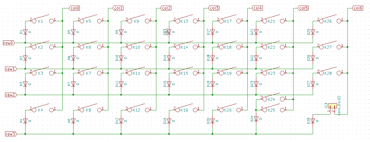
In the image above, we see that this keyboard has a matrix of 4 rows, with 7 columns. The direction of the diodes goes from the columns to the rows. With this information, we can define the following:
#define MATRIX_ROWS 4
#define MATRIX_COLS 7

#define DIODE_DIRECTION COL2ROW
Next, we need to identify how each row and column are mapped to the microntroller on board of the nRF52 module you use. Since most DIY keyboards use the Arduino Pro Micro as its controller, we are using such an example.
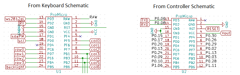
With the information from both the keyboard and controller schamatics, we can map each row and column to the GPIO and using the formula shown in the previous section, we can define the configuration needed:
#define MATRIX_ROW_PINS {13, 24, 9, 10 }
#define MATRIX_COL_PINS {26, 29, 2, 45, 3, 28, 43 }
Status LEDs
Most controllers will have 1 or 2 LEDs to let the user know of the status of the board. To configure the firmware to use these LEDs, you need to set at least the PIN definition for the LED.
By default, when STATUS_BLE_LED_PIN or STATUS_KB_LED_PIN are defined, both the ACTIVE and POLARITY settings will default to 1.
    #define  STATUS_BLE_LED_PIN  19  //blue = 0.19
    #define  BLE_LED_ACTIVE 1
    #define  BLE_LED_POLARITY 1

    #define  STATUS_KB_LED_PIN 17  //red = 0.17
    #define  STATUS_KB_LED_ACTIVE 1
    #define  STATUS_KB_LED_POLARITY 1
If you want to keep the definition of the PIN but want to disable the use of the specific status LED, you need to set the ACTIVE to 0.
By default, setting a 1 on the GPIO will turn on the LED. If this logic is reversed, set POLARITY to 0.
If your board does not have the LED defined but it's status does not change, you need to configure the PIN so that it can be updated to match the state of the keyboard.
Note that when going to sleep, the enabled pins will go in a low power mode (INPUT) and will turn off the LEDs.
Battery Monitoring
Battery Monitoring is a function that's specific to the controller you use. Most controllers implement an on-board battery charger and battery monitoring voltage divider and connect this divider to an analog input. Such a configuration is shown below:
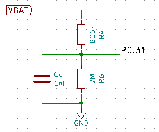
From the schematic, we identify that the connection point of the voltage divider is connected to 0.31. This leads to this definition:
#define BATTERY_TYPE BATT_LIPO
#define VBAT_PIN  31
If a non-rechargeable CR2032 (3V) powers your keyboard and the battery is directly connected to the nRF5 chip through VDD, you don't need to define a VBATT_PIN but since the nrf52 chip can measure its own supply voltage, it will not use this configuration. All you need to do is to use this definition:
#define BATTERY_TYPE BATT_CR2032
If a Lithion Ion (LiPo) rechargeable battery (3.7-4.2V) powers your keyboard and the battery is directly connected to the nRF52840 chip through VDDH, you don't need to define a VBATT_PIN since the nrf52 chip can measure its own supply voltage All you need to do is to use this definition:
#define BATTERY_TYPE BATT_VDDH
Note that only the nRF52840 has VDDH to provide power at a voltage higher than 3.6V.
External VCC Switching
Some controllers implement switching of external VCC to ensure low power consumption. Polarity of switching will depend on the hardware implementation. Refer to the controller documentation and/or schematic to identify if VCC switching is available, which GPIO it is connected to and polarity of the switch.
#define VCC_PIN 12
#define VCC_POLARITY_ON 1
If VCC_PIN is left undefined, VCC switching functionality will not be enabled in the firmware.
By default, VCC_POLARITY_ON is defined with 1. You only need to define it if polarity is reversed. (replace 1 with 0)
By default, the firmware will turn on external VCC when booting up and will turn off External VCC when going to sleep. If you want to force external VCC to be off at bootup, you can add this definition to your hardware_config.h file.
#define VCC_DEFAULT_ON 0
LiPo Charger Switching
Some controllers implement turning off the LiPo Charger to allow for a more precise battery level measurement. Switching polarity will depend on the hardware implementation. Refer to the controller documentation and/or schematic to identify if charger switching is available, which GPIO it is connected to and polarity to enable charging.
     #define CHARGER_PIN  5
     #define CHARGER_POLARITY_ON 0
If CHARGER_PIN is left undefined, charger switching functionality will not be enabled in the firmware. By default, the firmware will turn on charger when booting up and will not change it at any time.
Backlight PWM LED Definition
Some keyboards have backlit keys using LEDs controlled by a central mosfet. The brightness of these LEDs can be modulated using Pulse Width Modulation (PWM). When referring to the keyboard and controller schematics above, we see that GPIO 1.06 is connected to the LED Backlight.
This enables setting up the following configuration:
    #define BACKLIGHT_LED_PIN 38
    #define BACKLIGHT_PWM_ON 1
    #define DEFAULT_PWM_VALUE 10000  // Reduce max PWM to 10000 out of 63351 (0x7FFF)
If BACKLIGHT_LED_PIN is left undefined, LED functionality will not be enabled in the firmware.
BACKLIGHT_PWM_ON is optional. If BACKLIGHT_LED_PIN is defined, but you want to turn off LED functionality, you can do so by setting BACKLIGHT_PWM_ON to 0.
If DEFAULT_PWM_VALUE is left undefined, the default value will be that of maximum PWM value of 63351 (0x7FFF). This will turn on LEDs on fully.
Turning on the PWM peripheral on the nRF52 chip uses approximately 0.5mA, not including the power used by the LED themselves. As such, when the PWM value is set to 0, the firmware turns off the PWM peripheral it uses for controlling the brightness of the LEDs. It does the same prior to going to sleep.
RGB LED Definition
Some keyboards have RGB LEDs. These LEDs are controlled through a single data line. When referring to the keyboard and controller schematics above, we see that GPIO 0.06 is connected to the RGB WS2812 LEDs.
This enables setting up the following configuration:
    #define WS2812B_LED_PIN 6
    #define WS2812B_LED_COUNT 1
    #define WS2812B_LED_ON 1
If WS2812B_LED_PIN is left undefined, LED functionality will not be enabled in the firmware.
If WS2812B_LED_ON is set to 0, RGB functionality will not be enabled in the firmware. Note that this will not power down VCC power to the RGB LEDs, impacting power consumption of your keyboard. External VCC to the RGB LEDs is controlled through the External VCC Switch functionality described above.
OLED Definition
OLED displays are implemented using the U8g2 Library and assumes that the display uses I2C as the communication interface. This interface is defined by the SDA and SCK pins. For all keyboards designed to work with Arduino Pro Micros, these relate to the D1 and D0 AVR ports. nRF52 chips can relocate this interface to other GPIOs.
    #define I2C_SDA_PIN 15
    #define I2C_SCK_PIN 17
    #define DISPLAY_U8G2_CONSTRUCTOR U8G2_SSD1306_128X32_UNIVISION_F_HW_I2C // see https://github.com/olikraus/u8g2/wiki/u8g2setupcpp for reference
Since the U8g2 library supports a large number of displays by changing the type (hence changing the constructor method), changing the disply type is as simple as selecting a different constructor. See the u8g2 setup documentation for more information. The firmware assumes hardware I2C as parameters passed to the constructors.
Rotary Encoder Definition
Hardware quadrature decoder only supports a single Rotary encoder per side/half. If you need more than 1 encoder, you can use the software (interrupt driven) quadrature decoder, which supports up to 8 encoders per side.
Add these lines to your hardware_config.h if you use a single encoder.
#define ENCODER_A_PIN  26
#define ENCODER_B_PIN  30
#define ENCODER_RESOLUTION 2
If you use multiple encoders, you can expand the above to an array as follows:
#define ENCODER_PAD_A  {26, 8, 15, 17, 9 }
#define ENCODER_PAD_B  {6, 29, 2, 20, 13 }
#define ENCODER_RESOLUTION 2
From a hardware point of view, the A an B lines of the encoder should be wired directly to the nRF52 GPIO. The C (or common) line should be wired to ground. By default, the configuration uses the hardware QDEC peripheral (Quadrature Decoder) that's part of the nRF52 SoC and uses callbacks to handle rotation. If you need more than 1 encoder (per side) you will need to use the software implemention.
Encoder resolution is used within the encoder callbacks to divide the steps in case you get multiple steps per click.
Speaker/Buzzer/Audio Definition
Audio functions are based on the Tone functionality of the Adafruit nRF52 Arduino Core. They send a PWM Signal to the SPEAKER_PIN GPIO. If SPEAKER_PIN is not defined, audio functions won't work. Add this line to your hardware_config.h
#define SPEAKER_PIN 10
With only this definition, you will have basic audio feedback functionality enabled.